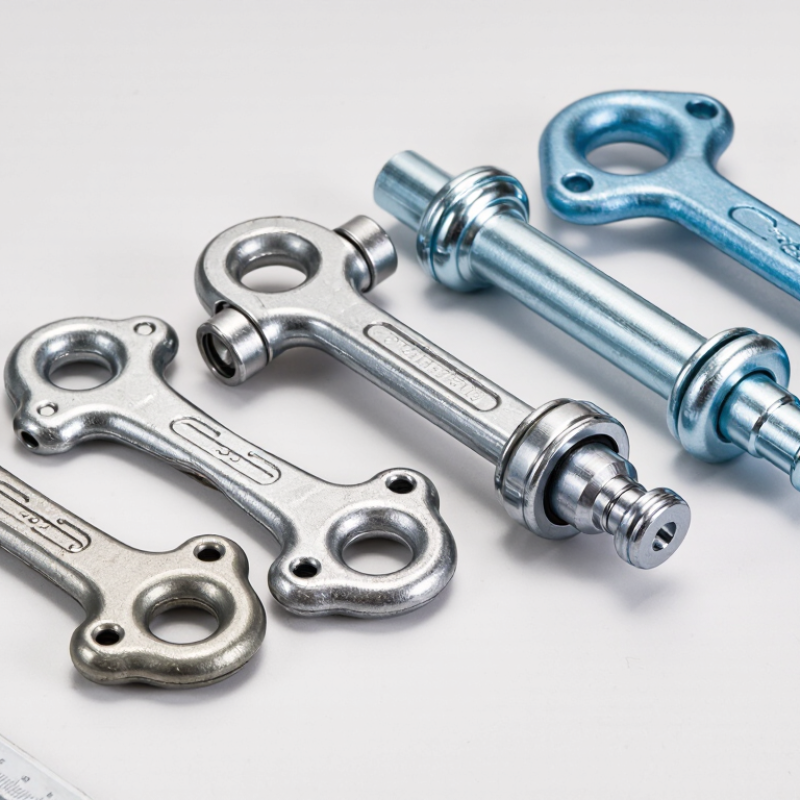
| 1. Axial-load lifting profile | Precast units lifted with the force acting close to the intended anchor axis. | Confirm the permitted load direction, anchor orientation, concrete strength at lift, and load share between lifting points. | Addresses safety requirements for non-fixed load lifting attachments within its scope; it does not establish a project-specific concrete capacity by itself. | Chapter 17 provides provisions for anchoring to concrete. Apply the relevant design method and check the actual anchor configuration and concrete conditions. | Rated-load documentation, installation instructions, and the required concrete strength at time of lifting. |
| 2. Angled-pull lifting profile | Lifting arrangements where sling geometry can introduce an inclined force at the anchor. | Use the system’s documented angle limits and capacity reductions; consider the resulting tension, shear, and possible prying or bending effects. | Supports safe use of lifting attachments; the permitted operating configuration must be established from applicable requirements and system documentation. | Check the applicable tension and shear actions and their interaction under the chosen Chapter 17 design approach. | Angle-dependent load data, approved sling arrangements, and installation details. |
| 3. Thin-element profile | Relatively thin precast panels or members with limited embedment depth. | Verify the minimum member thickness, embedment, reinforcement arrangement, and required edge distances; do not infer capacity from anchor dimensions alone. | Relevant to the lifting attachment’s safe use where the attachment falls within the standard’s scope; it does not replace member design. | Assess applicable concrete failure modes and the effect of member geometry using the adopted code provisions and project design assumptions. | Minimum member dimensions, embedment requirements, and reinforcement or supplementary reinforcement details. |
| 4. Edge-proximity profile | Anchors positioned near a free edge, opening, corner, or neighboring anchor. | Check edge distance, spacing, member boundaries, and interaction between nearby anchors. Reduced geometry can affect concrete breakout resistance. | Does not determine the concrete edge-breakout resistance of a particular installation. | Chapter 17 includes concrete anchorage checks; evaluate edge and spacing effects for the actual layout. | Approved placement drawings, minimum edge and spacing dimensions, and project-specific calculations. |
| 5. Higher-demand lifting profile | Heavier units or lifts involving significant handling, rotation, or other project-defined load effects. | Establish the design actions for the complete lift, including applicable dynamic effects, unequal load sharing, and the weakest part of the lifting load path. | Informs safety requirements for applicable lifting attachments; it is not a substitute for calculating project lifting actions. | Use the applicable design provisions to check the concrete anchorage for the calculated actions; confirm the adopted ACI 318 edition and project requirements. | Design basis, rated capacities for the intended configuration, and a documented lift calculation. |
| 6. Repeated-handling profile | Components expected to be lifted more than once during production, storage, transport, or erection. | Confirm whether repeated lifting is permitted, define inspection and discard criteria, and check for damage, corrosion, and changes in the lifting arrangement. | Provides lifting-attachment safety context within its scope; follow the applicable instructions for inspection and use. | Concrete anchorage design still depends on the installed configuration and design actions; ACI 318 is not an inspection program for lifting gear. | Written reuse limits, inspection guidance, traceability information, and maintenance requirements. |
| 7. International-project profile | Projects involving cross-border procurement, multiple design teams, or different national approval requirements. | Match the anchor’s declared use, drawings, material and installation requirements, and calculations to the governing project jurisdiction and lifting plan. | Check the applicable edition, scope, and local adoption; do not assume that reference to EN 13155 alone demonstrates approval for every market or installation. | Use the ACI 318 edition specified by the project or authority having jurisdiction. ACI 318 concrete design provisions do not replace lifting-equipment requirements. | Applicable declarations or certifications, design calculations, language-appropriate instructions, and confirmation of local acceptance. |