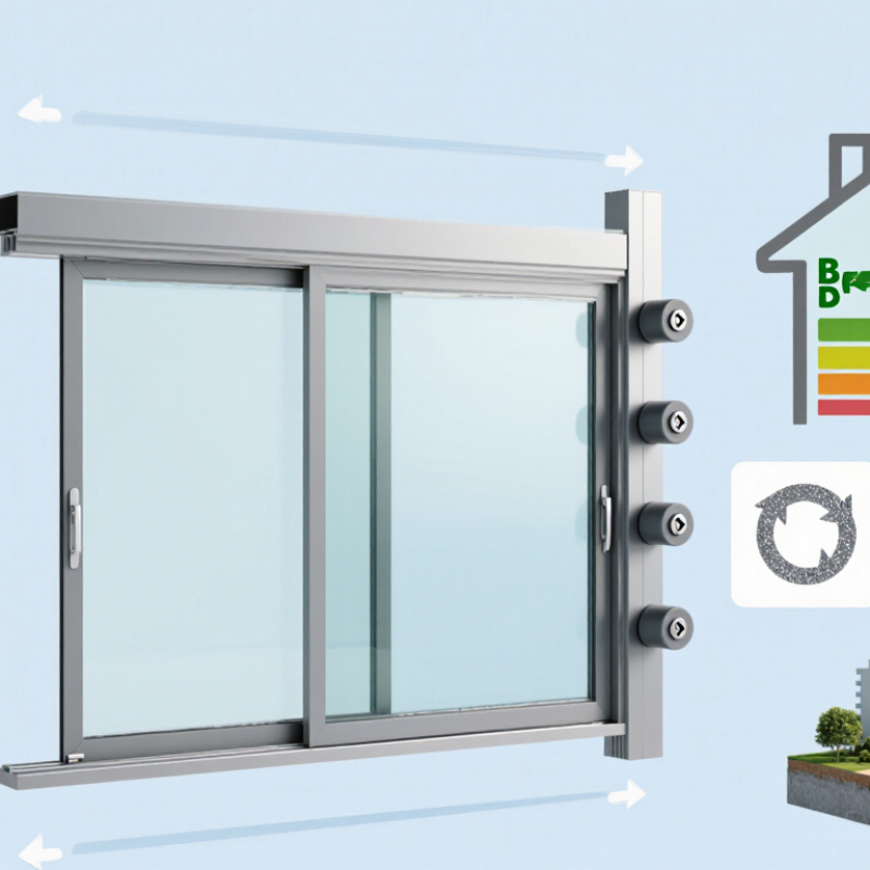
| Aluminum sliding door profile | An extruded aluminum component that forms part of the door frame, sash, track, meeting stile, sill, or glazing surround. | Profiles are assembled into the fixed frame and moving panels, then combined with seals, rollers, drainage paths, glazing, and hardware. | EN 12020-1 and EN 12020-2 are commonly used for precision aluminum extrusion requirements and dimensional tolerances. | The standard addresses profile quality and tolerances; it does not assign a complete door air, water, wind, or thermal rating. | Accurate profiles help maintain alignment, consistent gasket compression, reliable glazing installation, and smooth panel movement. |
| Profile dimensional accuracy | The ability of an extruded profile to remain within specified limits for dimensions, form, straightness, and twist. | Important for frame corners, interlocking meeting stiles, track sections, and gasket channels. | EN 12020-2 provides dimensional and form tolerances for applicable precision-extruded aluminum profiles. | Tolerance values depend on the profile dimension, cross-section, wall thickness, and specified tolerance class. | Better dimensional control reduces gaps, binding, uneven seal compression, and installation problems. |
| Thermal break | A low-conductivity polyamide or similar insulating barrier that separates the exterior and interior aluminum sections. | Used mainly in the frame, sash, threshold, and meeting stile of thermally improved sliding doors. | Thermal performance is assessed through U-value calculations or testing under standards such as EN ISO 10077-1 and EN ISO 10077-2. | A thermally broken aluminum frame may have a frame U-value (Uf) of approximately 1.5–3.0 W/m²K, depending on geometry and system design. Non-thermally broken frames are commonly much higher, often about 5.0–7.0 W/m²K. | Reduces heat flow through the aluminum frame and lowers the risk of interior condensation in suitable designs. |
| Whole-door thermal transmittance | The combined heat-transfer rate through the frame, glass, spacers, sash, and other door components. | Used when comparing the energy performance of a complete sliding door rather than the aluminum profile alone. | EN ISO 10077-1 and EN ISO 10077-2 are commonly used for calculating door and window thermal transmittance. | A representative modern thermally broken glazed sliding door may achieve a Uw value of approximately 1.0–2.0 W/m²K, depending strongly on glazing, frame proportion, spacers, and size. | A lower U-value indicates lower heat transfer. The published value should always identify whether it is Uf, Ug, or Uw. |
| Glazing pocket and gasket channel | The profile area that supports the glass unit and receives glazing gaskets or seals. | Used around fixed and sliding panels to retain insulated glass units and create a continuous weather seal. | Glazing design is coordinated with the relevant product standards and the calculated thermal and weather performance of the complete door. | Compatible glazing thickness may range from single glazing to insulated glass units commonly around 24–52 mm, depending on the profile system. | Allows the use of thicker insulated glass, improves air and water sealing, and can reduce the overall Uw value. |
| Air permeability | Resistance of the closed door to unwanted air leakage caused by pressure differences. | Controlled by seals, corner joints, interlocks, drainage design, frame accuracy, and installation quality. | EN 12207 classifies air permeability for doors and windows. Testing is generally performed according to EN 1026. | Classes range from 1 to 4; Class 4 represents the highest air-permeability performance in the EN 12207 classification system. | Higher air-tightness can reduce drafts, external noise paths, energy loss, and moisture movement through unintended gaps. |
| Water tightness | The ability of a closed door assembly to resist water penetration during simulated wind-driven rain. | Dependent on sill height, drainage channels, weep holes, gaskets, corner joints, panel overlap, and installation details. | EN 12208 classifies water tightness. Testing is generally performed according to EN 1027. | Common classifications include 1A–9A for exposed installation conditions; special classifications such as 5B may also be used for less exposed situations. | Effective drainage and correctly compressed seals direct water away from the interior and reduce leakage risk. |
| Wind load resistance | The ability of the complete door to resist wind pressure and suction without unacceptable deformation, damage, or loss of function. | Influenced by profile depth, wall thickness, reinforcement, panel size, glass weight, anchorage, and the number of locking points. | EN 12210 provides wind-load classification. Testing is generally performed according to EN 12211. | Classes range from 1 to 5 for pressure and deflection categories; a higher class indicates greater tested resistance. Deflection classes may be A, B, or C. | Stronger profiles and secure anchorage limit bowing, preserve seal contact, and help the panels continue to operate under wind pressure. |
| Sliding track and roller support | The lower profile and hardware interface that carries the weight of the moving panel. | Used in single-track, double-track, or multi-track sliding configurations. | Performance depends on the complete hardware and door-system design rather than on extrusion dimensions alone. | Typical glazed sliding panels may weigh several hundred kilograms; the allowable panel weight must be confirmed from the selected roller and hardware specification. | Correct track geometry and load capacity provide smoother operation, lower wear, and reduced risk of panel misalignment. |
| Meeting stile and interlock | The vertical profile where two sliding panels meet or where a panel engages with the fixed frame. | Used to create overlap, accommodate seals, and integrate locks or pull handles. | Air, water, and wind performance is verified on the complete assembled door, including the interlock and hardware. | The interlock geometry must provide continuous seal contact while allowing the required operating clearance. | Improves air tightness, weather resistance, security integration, and resistance to wind-induced movement. |
| Drainage and sill design | Channels and outlets that collect and discharge water from the sill and glazing zones. | Used at the lower frame, track, glazing pocket, and panel intersections. | Water tightness is evaluated as part of the complete assembly under EN 12208 testing procedures. | Drainage openings must remain unobstructed and should be coordinated with the installation substrate and external sill conditions. | Reduces water accumulation, protects seals and finishes, and helps prevent interior leakage during wind-driven rain. |
| Installation and anchorage | The method used to connect the aluminum frame to the surrounding wall and transfer structural loads. | Includes fixing points, packers, perimeter seals, movement joints, sill support, and weatherproof interfaces. | Laboratory classification applies to the tested product configuration; site installation must follow the project design and applicable building requirements. | The final installed performance can be lower than the laboratory rating if the frame is distorted, poorly supported, or inadequately sealed. | Correct installation preserves frame geometry and allows the tested air, water, wind, and thermal performance to be approached in practice. |