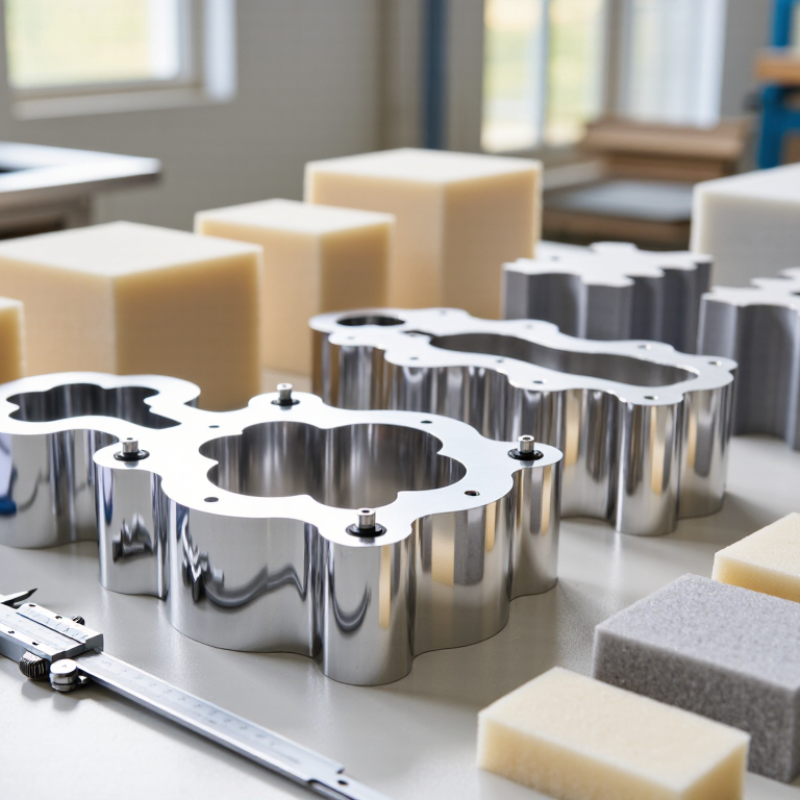
| Mould Tool Material | Cast or machined aluminum | Approx. 2.60–2.75 g/cm³ density; high thermal conductivity compared with steel | Supports faster heat transfer, shorter thermal response time, and easier manual handling for medium-sized cushion moulds. | Check alloy selection, wall thickness, distortion control, weld repair quality, and surface hardness requirements. |
| Alternative Tool Material | Steel or aluminum-steel hybrid construction | Used when higher wear resistance, repeated production, or heavy clamping loads are required | Offers higher rigidity and durability but generally increases tool weight, machining time, and handling requirements. | Match material choice to production volume, cushion size, cycle temperature, and expected tool life. |
| Cavity Surface Finish | Machined, polished, textured, or grain-etched surface | Surface specification should be defined by roughness, texture pattern, and visual sample approval | Influences skin appearance, demoulding behavior, gloss level, and the visibility of surface imperfections. | Approve a representative surface coupon or first-off sample before full tool finishing. |
| Venting Arrangement | Vent grooves, vent pins, porous inserts, or perimeter venting | Vent locations are normally concentrated at high points, deep ribs, corners, and last-fill areas | Helps release trapped air and reduces voids, incomplete filling, surface pitting, and localized density variation. | Review vent accessibility, cleaning method, vent depth, and the risk of visible witness marks on the cushion skin. |
| Vent Maintenance | Cleanable mechanical vents and replaceable vent inserts | Inspection frequency depends on foam chemistry, moulding cycle, and release-agent build-up | Maintains consistent filling and reduces process drift caused by blocked or contaminated vent paths. | Require a documented cleaning procedure and an inspection checklist for production operators. |
| Release-Agent Type | Water-based, solvent-based, or semi-permanent release system | Selection depends on foam formulation, mould temperature, surface finish, and transfer limits | Affects demoulding force, surface appearance, coating transfer, paint adhesion, and cleaning frequency. | Validate release performance using the actual foam formulation and the intended production temperature. |
| Release-Agent Application | Manual spray, automated spray, wipe-on, or pre-coated surface | Application must be uniform; excessive build-up can alter texture and cause surface defects | Consistent application improves cycle repeatability and reduces sticking, tearing, and dimensional variation. | Define coverage method, drying time, reapplication interval, and acceptable surface residue. |
| CAD Data Format | Parametric 3D CAD with 2D manufacturing drawings | Common exchange formats include STEP, IGES, Parasolid, and native CAD files | Supports design review, cavity interference checks, parting-line definition, and CNC programming. | Confirm the coordinate system, revision status, material shrinkage allowance, and drawing tolerances. |
| CAD Accuracy Control | CAD-to-CAM verification and inspection against the approved digital master | Typical general machining tolerances are often around ±0.05 to ±0.20 mm, subject to feature size and process | Improves cavity alignment, cushion symmetry, repeatability, and consistency between mould halves or matched tools. | Request a dimensional inspection report identifying critical cavity, insert, and alignment features. |
| Shrinkage Compensation | Formula-specific scaling and trial-based adjustment | The correct factor depends on foam density, chemistry, temperature, packing, and cure conditions | Helps achieve the required finished cushion dimensions after demoulding and conditioning. | Do not use a universal factor; establish compensation from validated material and process trials. |
| Parting-Line Design | Visible-edge, hidden-edge, or functional split-line layout | Position is selected to control flash, demoulding direction, appearance, and tool access | Influences flash removal time, seam visibility, tooling complexity, and the risk of tearing during release. | Evaluate the parting line with a physical cushion sample and confirm operator access for trimming. |
| Alignment System | Guide pins, bushings, tapered locators, or precision dowels | Alignment hardware should be replaceable and protected from foam contamination | Maintains cavity registration, reduces mismatch, and protects the finished cushion from uneven split-line marks. | Check alignment repeatability after repeated opening and closing cycles. |
| Temperature Management | Internal heating channels, external heating plates, or controlled ambient curing | The required temperature profile is formulation-specific and must be validated by process trials | Supports consistent reaction, curing, skin formation, density distribution, and cycle time. | Review temperature uniformity across the cavity rather than relying only on one sensor location. |
| Tool Validation | First-article trial, dimensional inspection, visual approval, and repeated-cycle test | Validation should cover dimensions, density, surface quality, flash, release behavior, and cycle stability | Identifies design or process problems before regular production and reduces later modification costs. | Use an agreed acceptance sheet with measurable criteria and approved reference samples. |
| Supplier Capability Review | Design engineering, CNC machining, finishing, trial moulding, and after-sales modification support | Capability should be assessed by documented equipment, inspection methods, and relevant moulding experience | Reduces communication gaps between CAD design, tooling manufacture, foam trials, and production launch. | Compare technical evidence and sample results rather than relying only on quoted price or delivery claims. |